| Brief Description | |
|---|---|
|
Files: \examples\Processing\ObjectFeatures\PrintInspection\PrintInspection_ImageMoments.vad |
 |
|
Default Platform: imaFlex CXP-12 Quad |
|
|
Short Description Image moments based position correction and defect detection via blob detection |
|
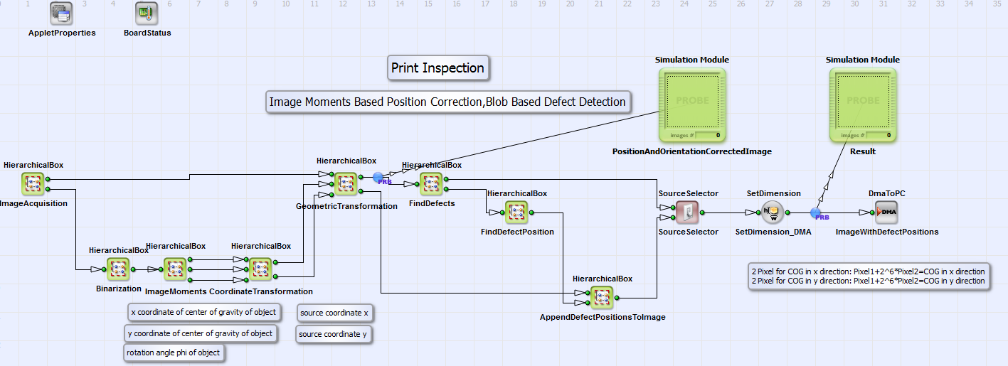
A position and orientation correction of an object and subsequent defect detection is performed in the design "PrintInspection_ImageMoments.vad". The example is suitable for objects with no imprints. You can see the basic design structure in Fig. 384. The acquired image object is binarized in the HierarchicalBox Binarization and via image moments (see theory in section ) the orientation and position of the object is determined (content of box ImageMoments). The parameter for the binarization threshold is suitable for the example image "testImage.tif". If you use your example image please adapt the binarization threshold. A geometric transformation is performed to correct position and orientation equivalent to the example "GeometricTransformation_ImageMoments" (see section ). The detection of defects and their coordinates (in boxes FindDefects and FindDefectPosition) is equivalent to the defect detection in the print inspection example "PrintInspection_Blob.vad" (see section ). The user can choose whether he/she wants to send an image with the pure defects or the combined image (position and orientation corrected image together with the defects coordinates as output from box AppendDefectPositionToImage) to PC in setting the parameter "SelectSource" of the operator SourceSelector to 0 or 1.

